Facade Insights · 2026
Rainscreen Transition Detailing at Parapets, Soffits, and Reveals
At parapets, soffits, and recessed reveals, a rainscreen stops behaving like a repetitive wall field. The cavity changes direction, the cladding support geometry becomes more constrained, and the wall must connect to roofing, glazing, waterproofing, or another enclosure assembly. These transitions concentrate design responsibility: a visually clean edge still has to preserve drainage, air and water control, thermal continuity, movement capacity, and installation access.
The broader principles of panelized rainscreen systems remain the same at every condition, but they must be translated into buildable, condition-specific details. For experienced project teams, the question is not whether each control layer exists. It is whether the layers connect in the correct order and whether the panels, subframing, flashings, membranes, and adjacent systems can be installed as drawn.
Parapets: Coordinate the Wall-to-Roof Transition
A parapet is not simply the top termination of the cladding. It is the point where the wall's water, air, vapor, and thermal control layers must connect to the corresponding roof layers. Building Science Corporation's guidance on parapets and roof-to-wall continuity emphasizes connecting these control functions instead of treating the roof and wall as independent assemblies.
For rainscreen detailing, several related conditions must be resolved together:
- Continuation of the air/water barrier behind or beneath the coping
- Termination and drainage of the rainscreen cavity
- Support of the uppermost panel without blocking required clearances
- Coping joints, slopes, cleats, and drips at both parapet faces
- Protection and accessibility of roofing membrane terminations
- Differential movement between the coping, cladding, and backup wall
The coping should not be expected to compensate for incomplete membrane continuity below it. Similarly, a continuous closure added for appearance may unintentionally obstruct cavity drainage or ventilation. The detail must distinguish the exposed water-shedding components from the concealed drainage and air-control layers.
Lavada's facade design-assist services address parapets as coordinated assemblies, aligning coping geometry, panel modules, subframing, roofing interfaces, and installation sequence before fabrication dimensions are finalized.
Resolve high-risk facade transitions before they become fabrication or field conflicts. Discuss your project
Soffits: Prevent Water Accumulation at Horizontal Transitions
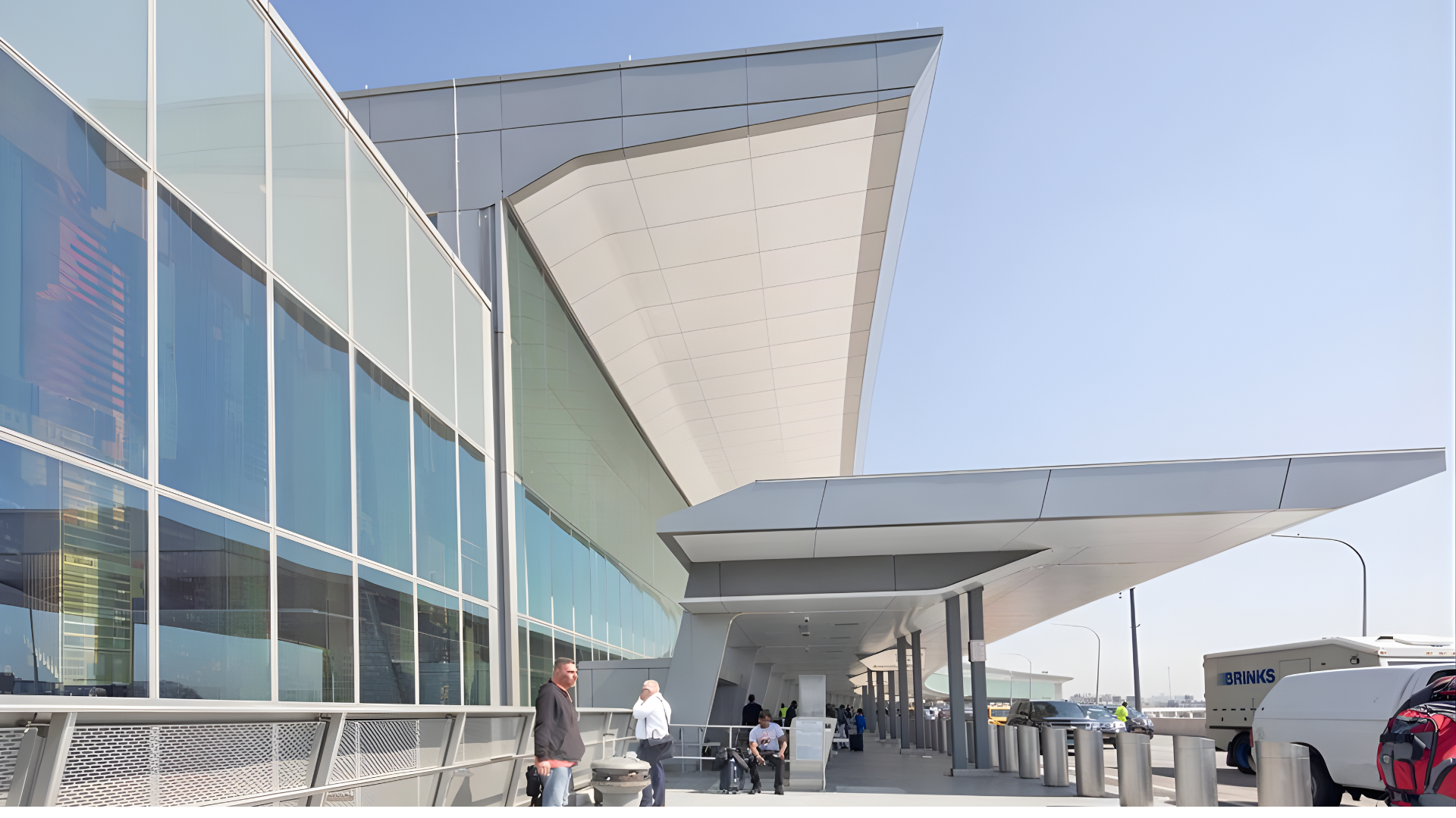
Soffits create a transition from vertical to horizontal, or sloped, cladding and frequently introduce canopies, entrances, balconies, lighting, louvers, sprinklers, signage, and structural penetrations. The condition may appear simple in elevation while remaining congested in section.
A successful rainscreen soffit detail establishes where water from the wall cavity is discharged before the assembly turns inward. Water should not be directed into a horizontal cavity without a defined outlet. Wall flashing, end dams, membrane transitions, and vent or closure configurations must work together so the soffit does not become a collection zone.
Support geometry also requires early coordination. Vertical wall rails may not continue efficiently across the return, and the soffit may require independent framing, engineered attachments, or a revised clip orientation. Panel dimensions and joint locations should correspond to accessible fastening points rather than forcing concealed field modifications.
Openings within the soffit require the same discipline. Light fixtures, drains, vents, cameras, and other penetrations should be coordinated with panel joints and framing, with responsibility for membrane seals and perimeter trims clearly assigned.
Lavada coordinates these conditions through engineering, fabrication modeling, and facade shop drawings, allowing panelization and attachment access to be reviewed against adjacent systems before material reaches the field.

Reveals and Returns: Preserve Drainage Behind the Architecture
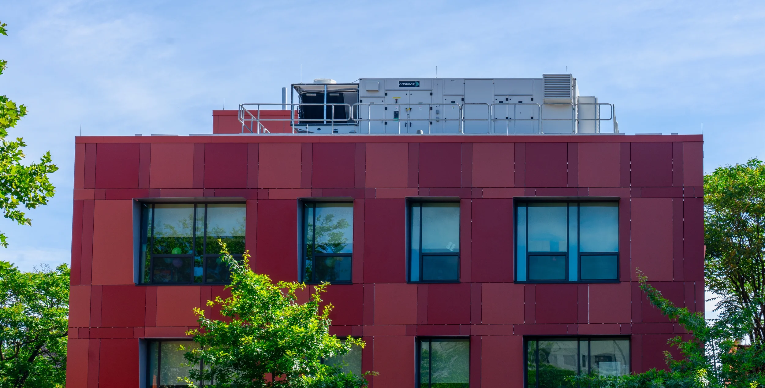
Deep window reveals, recessed entrances, expressed shadow lines, and framed openings interrupt the drainage plane while narrowing the space available for flashing and attachment. The architectural reveal may be designed as one continuous visual feature, but its head, jambs, and sill perform different enclosure functions.
At the head, flashing should collect water from above and project it back to the exterior with positive slope. Building Science Corporation's common flashing details recommend outward-sloped head flashing that extends beyond the sides of the opening.
At the sill, pan flashing must collect incidental water and discharge it outward rather than sealing the bottom in a way that traps moisture. The U.S. Department of Energy's guidance on fully flashed window and door openings similarly identifies sill flashing and back dams as part of directing water away from the rough opening.
For panelized systems, reveal depth also affects cassette returns, trim profiles, joint widths, clip engagement, insulation continuity, and replacement access. A narrow reveal may leave insufficient room to install fasteners or complete membrane laps. A deep reveal can amplify tolerance conflicts between the window location, backup wall, and panel grid.
These issues are best resolved with enlarged head, jamb, and sill details rather than one typical perimeter condition. The drawings should identify membrane sequencing, flashing extents, end dams, sealant locations, backer-rod geometry, subframing, panel edges, and the intended drainage path.
What Coordinated Transition Details Should Show
At minimum, the drawing set should make five items unambiguous:
3D transition sketches can be especially useful where parapets meet corners, soffits intersect curtain walls, or reveals connect to multiple cladding materials. They expose laps, end conditions, and installation conflicts that may remain hidden when the assemblies are documented only through separate two-dimensional details.
Lavada's panelized rainscreen work integrates engineering, shop drawings, fabrication, and installation around these interface conditions. That coordinated scope helps convert architectural transition concepts into repeatable panel geometry, defined flashing relationships, and field sequences that do not depend on improvisation.
Detail the Transition Before It Becomes a Field Decision
Parapets, soffits, and reveals are high-risk because several systems converge within limited space, not because they require unusually complicated components. The strongest details establish continuity, drainage, support, movement, and sequencing together.
When those decisions are made during design assist and carried consistently into fabrication and installation documents, transition conditions can remain both technically controlled and visually precise.
Lavada provides integrated design-assist, engineering, fabrication, and installation support for detail-sensitive commercial facade transitions.
Get in touchFrequently Asked Questions
Why are parapets, soffits, and reveals high-risk rainscreen conditions?
These transitions concentrate changes in cavity direction, flashing, membranes, subframing, adjacent assemblies, and installation access. Performance depends on coordinating those elements as one condition rather than resolving each component independently.
What should a rainscreen parapet detail show?
A parapet detail should show the continuous air and water control path, roof-to-wall membrane transition, coping support and joints, cavity termination, panel attachment, drainage route, movement allowances, and a practical installation sequence.
How should drainage be handled where a wall turns into a soffit?
Water from the vertical cavity should be discharged through a defined flashing and drainage path before the assembly turns inward. Closures, vents, end dams, and membrane transitions should prevent the horizontal cavity from becoming a collection zone.
Why should window heads, jambs, and sills be detailed separately?
Each part of the opening performs a different function. The head redirects water, the jambs maintain continuity around the opening, and the sill collects and discharges incidental water. Separate details also clarify panel returns, flashing extents, attachment access, and tolerance management.